Component Placement in Allegro PCB Editor
Article published Nov 16th 2022!
Circuit board design is often considered an art as there is no formula to producing quality content. The designer often makes several iterations before they are satisfied with their work. In hopes to minimize the number of revisions a critical task that should be done diligently is the initial floorplan analysis. Having a well thought-out plan on placement of the large active components will allow for a successful project completion.
Typically the most complex component is also the most power hungry which means it's thermal profile needs to be considered. This area of the PCB will be hotter so being mindful of heat dissipation strategies and minimizing impact to surrounding parts is recommended. In addition, depending on the communication interfaces, the placement will determine the interface speed as long channels degrade signal quality and are prone to bit errors. Allegro PCB Editor along with the simulation tools have the capability to perform such analysis to determining optimal placement but often enough, intuition and logic are sufficient in approximating the general area for these critical components.
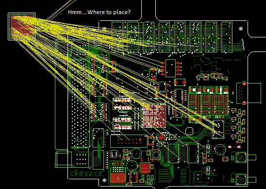
There are several methods for executing the task of component placement in Allegro PCB Editor. The designer can choose to place each component individually or take advantage of some of the semi-automated features.
Manual Placement
This method provides precision when it comes to finding the appropriate location for each component. Once a component is selected within the Placement window, it's footprint then follows the cursor and can be dropped either on the top side of the board or mirror and placed on the bottom side. Live design rule checking (DRC) is an excellent feature that ensures components are not violating their spacing constraints - whether it's proximity to other components or certain keep-out/keep-in regions. Once a component is placed on the canvas, the next one in the list is automatically selected and so forth. If the default selection list is not preferred, there is the option to reorganize based on component properties, net connectivity, or even schematic page numbering. This provides a more intuitive approach to placing components that all belong in a specific region rather than jumping across the whole design in a somewhat random fashion.
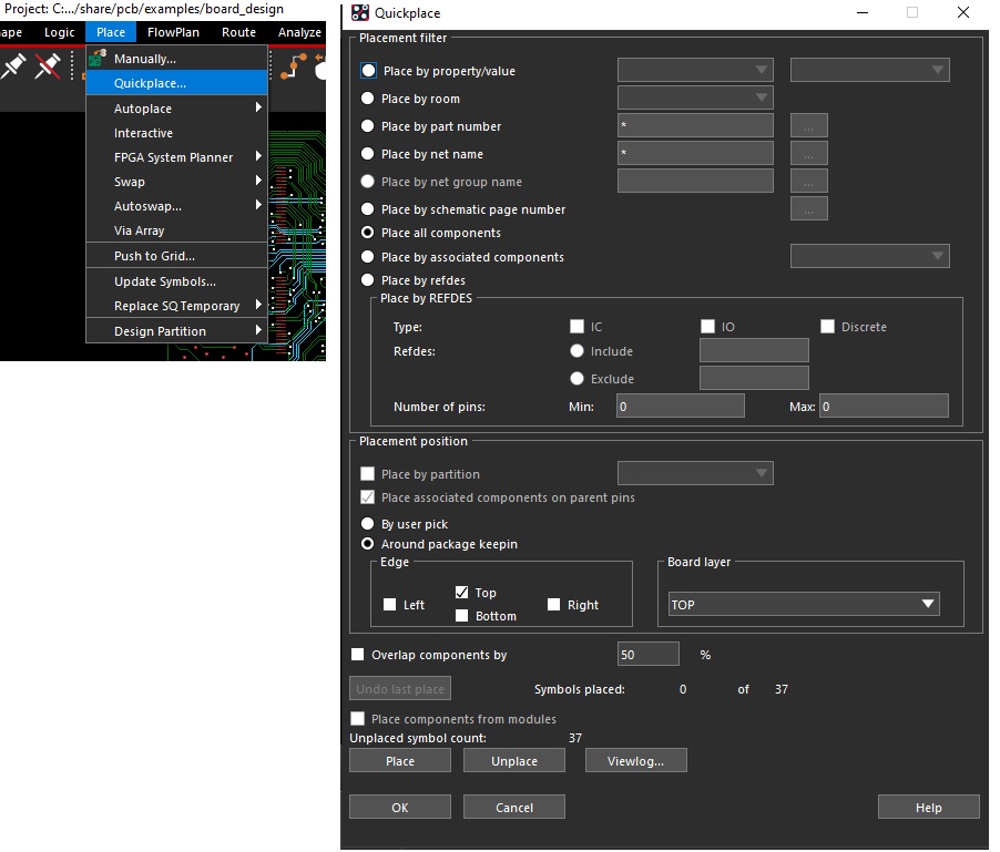
Quick Placement
The quick placement feature automates this task such that individual actions are not needed for each component. Parameters such as component properties, net connectivity, or schematic page numbering can be utilized to give the EDA tool instructions on how the placement should occur. The positioning of each part is typically immediately next to each other and adjustments are made after all components are visible on the design canvas. The live DRC is active when moving any component that has a DFA_DEV_CLASS property as per the DFA table constraints.
Summary
If the designer is puzzled as to which approach should be taken when it comes to placing components, knowing that the effort involved is the same should reduce some anxiety. More up-front work is necessary when pursuing the manual placement method to ensure each part is dropped at an ideal location whereas the quickplace drops all parts on the canvas in an unintelligent fashion and then the designer reorganizes them as necessary. The execution is no doubt a tedious task regardless of which method is deployed but it can be minimized to a single iteration if the initial floorplan is assessed carefully. Minor adjustments are inevitable but if complex critical components are placed in a non-ideal location then expect a multiple-fold effort to be necessary to not only correct the placement but also to rip up any routing tasks that have been completed.


Comments
Add your comments in the section below